


Page 67 - Demo
P. 67
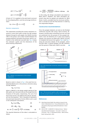
AAC WORLDWIDE %u2022 2.2026 APPLICATION & CONSTRUCTION 65A factor of 1.5 is applied to the wind load to account for the whipping effect, and the anchorage reinforcement:Resistor componentsThe components providing the contact mechanics required to resist wind loads include the AAC parapet element through its self-weight, the C20/25 concrete infill in the groove, and a rebar located between the parapet elements and within the groove, which is anchored to the reinforced concrete slab. Fig. 5 shows the schematic system and the dimensions of the wind-resisting components.Based on what is shown in Fig. 5, the axial force labeled Nz (kN/m) acts in the vertical z-direction along the AAC element.where %u03b3 (kN/m%u00b3) is the design weight density of the AAC panel, and l (m) and d (m) are the length and the thickness of the panel, respectively. The sum of all the friction forces is Rz (kN/m) that will be calculated from the Equation 7. W* in Equation 8 represents the wind load reduced for friction effects and is used in the subsequent calculations.The required dimension of the rebar is calculated as beloIn this study, the design assumption was based on Wind Zone 2. However, the same calculation approach may also be applied and adjusted for Wind Zones 3 and 4, provided that the structural verification is carried out and the final decision is made by the responsible designer.Constructive recommendationsFirst, the parapet elements are laid on the finished reinforced concrete slab using a bed of mortar. Afterward, the %u00d816 rebars extending from the roof slab are positioned into the grooves of the parapet elements. Once all elements are in place and properly aligned, the grooves are filled with C20/25 concrete to complete and secure the system. Fig. 6 and Fig. 7show the execution details of the parapets, where the %u00d816 rebar is placed between the AAC elements and the groove is filled with C20/25 concrete. %u25cfReferences[1] Xella Deutschland GmbH: Die einfache L%u00f6sung f%u00fcr den oberen Geb%u00e4udeabschluss: Ytong Attikaelemente, www.xella.de/de_DE/ytong/produkte/attikaelement, Stand 06/2025.[2] DIN EN 1991-1-4/NA:2010-12: National Annex %u2013 Nationally Determined Parameters %u2013 Eurocode 1: Actions on structures %u2013 Part 1-4: 99 General actions %u2013 Wind actions; Beuth-Verlag: Berlin, 2010.Fig. 7: The structural system under consideration and the parapet element connection to the RC slabFig. 5: Details and dimensions of the resistor componentsFig. 6: Recommended connection detail for parapet elements


