
Page 76 - Demo
P. 76
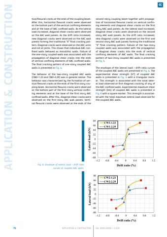
76 APPLICATION & CONSTRUCTION AAC WORLDWIDE %u2022 3.2025APPLICATION & CONSTRUCTIONtical flexural cracks at the ends of the coupling beam. After this, horizontal flexural cracks were observed on the bottom part of the vertical confining elements and at the base of AAC confined walls. As the lateral load increased, diagonal shear cracks were observed on the AAC wall panels. As the drift ratio increased, new diagonal cracks were observed on the AAC wall panels forming the traditional %u201cX%u201d final cracking pattern. Diagonal cracks were observed on the AAC units and not at joints. This shows that individual AAC confined walls behaved as monolithic walls. Failure of the one-story coupled walls was associated with the propagation of diagonal shear cracks into the ends of vertical confining elements of AAC confined walls. The final cracking pattern of one-story coupled AAC walls is presented in Fig. 4.The behavior of the two-story coupled AAC walls (CW2%u20131.23 and CW2%u20132.29) was in general similar. The behavior was characterized by the formation of vertical flexural cracks at the ends of the first story coupling beam. Horizontal flexural cracks were observed on the bottom part of the first story vertical confining elements and at the base of the first story AAC confined walls. After this, diagonal shear cracks were observed on the first story AAC wall panels. Vertical flexural cracks were observed at the ends of the second story coupling beam together with propagation of horizontal flexural cracks on vertical confining elements and diagonal shear cracks on the first story AAC wall panels. As the lateral load increased, diagonal shear cracks were observed on the second story AAC wall panels. As the drift ratio increased, new diagonal cracks were observed on the first and second story AAC wall panels forming the traditional %u201cX%u201d final cracking pattern. Failure of the two-story coupled walls was associated with the propagation of diagonal shear cracks into the ends of vertical confining elements of AAC walls. The final cracking pattern of two-story coupled AAC walls is presented in Fig. 5.The envelope of the lateral load %u2013 drift ratio curves of the coupled AAC walls are presented in Fig. 6. The experimental shear strength (VT) of coupled AAC walls is presented in Fig. 6 with a triangular marker. This strength is associated with the total lateral load observed at first diagonal cracking of any of the AAC confined walls. Experimental maximum shear strength (Vm) of coupled AAC walls is presented in Fig. 6 with a square marker. This strength is associated with the total maximum lateral load observed for the coupled AAC walls.Fig. 6: Envelope of lateral load %u2013 drift ratio curves of coupled AAC walls.
