
Page 74 - Demo
P. 74
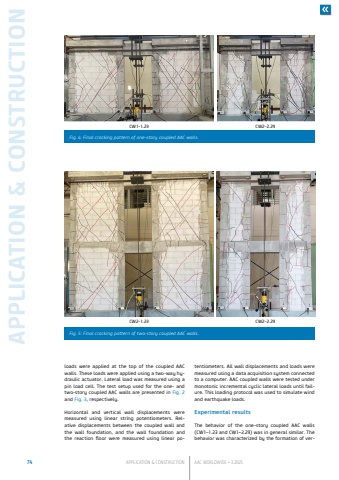
74 APPLICATION & CONSTRUCTION AAC WORLDWIDE %u2022 3.2025APPLICATION & CONSTRUCTIONloads were applied at the top of the coupled AAC walls. These loads were applied using a two-way hydraulic actuator. Lateral load was measured using a pin load cell. The test setup used for the one- and two-story coupled AAC walls are presented in Fig. 2and Fig. 3, respectively.Horizontal and vertical wall displacements were measured using linear string potentiometers. Relative displacements between the coupled wall and the wall foundation, and the wall foundation and the reaction floor were measured using linear potentiometers. All wall displacements and loads were measured using a data acquisition system connected to a computer. AAC coupled walls were tested under monotonic incremental cyclic lateral loads until failure. This loading protocol was used to simulate wind and earthquake loads.Experimental resultsThe behavior of the one-story coupled AAC walls (CW1%u20131.23 and CW1%u20132.29) was in general similar. The behavior was characterized by the formation of verCW1-1.23 CW2-2.29Fig. 4: Final cracking pattern of one-story coupled AAC walls.CW2-1.23 CW2-2.29Fig. 5: Final cracking pattern of two-story coupled AAC walls.
