
Page 26 - Demo
P. 26
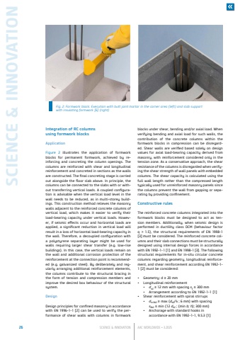
SCIENCE & INNOVATION26 SCIENCE & INNOVATION AAC WORLDWIDE %u2022 3.2025Integration of RC columnsusing formwork blocksApplicationFigure 2 illustrates the application of formwork blocks for permanent formwork, achieved by reinforcing and concreting the column openings. The columns are reinforced with shear and longitudinal reinforcement and concreted in sections as the walls are constructed. The final concreting stage is carried out alongside the floor slab above. In principle, the columns can be connected to the slabs with or without transferring vertical loads. A coupled configuration is advisable when the vertical load level in the wall needs to be reduced, as in multi-storey buildings. This construction method relieves the masonrywalls adjacent to the reinforced concrete columns of vertical load, which makes it easier to verify their load-bearing capacity under vertical loads. However, if seismic effects occur and horizontal loads are applied, a significant reduction in vertical load will result in a loss of horizontal load-bearing capacity in the wall. Therefore, a decoupled configuration with a polystyrene separating layer might be used for walls requiring larger shear transfer (e.g. low-rise buildings). In this case, the vertical loads remain on the wall and additional corrosion protection of the reinforcement at the connection point is recommended (e.g. galvanized steel). By deliberately and regularly arranging additional reinforcement elements, the columns contribute to the structural bracing in the form of tension and compression members and improve the desired box behaviour of the structural system.DesignDesign principles for confined masonry in accordance with EN 1996-1-1 [2] can be used to verify the performance of shear walls with columns in formwork blocks under shear, bending and/or axial load. When verifying bending and axial load for such walls, the contribution of the concrete columns within the formwork blocks in compression can be disregarded. Shear walls are verified based solely on design values for axial load-bearing capacity derived from masonry, with reinforcement considered only in the tension zone. As a conservative approach, the shear resistance of the columns is disregarded when verifying the shear strength of wall panels with embedded columns. The shear capacity is calculated using the full wall length rather than the compressed length typically used for unreinforced masonry panels since the columns prevent the wall from gapping or separating by providing confinement.Constructive rulesThe reinforced concrete columns integrated into the formwork blocks must be designed to act as tension members. Additionally, when seismic design is performed in ductility class DCM (behaviour factor q > 1.5), the structural requirements of EN 1998-1 [3] must be considered. The reinforced concrete columns and their slab connections must be structurally designed using internal design forces in accordance with EN 1992-1-1 [1] and EN 1998-1 [3]. The following structural requirements for in-situ circular concrete columns regarding geometry, longitudinal reinforcement, and shear reinforcement according EN 1992-1-1 [2] must be considered:%u2022 Geometry: d %u2265 20%u00a0mm%u2022 Longitudinal reinforcement%u2022 dsl%u00a0%u2265 12 mm with spacing sl %u2264 300 mm%u2022 Arrangement according to EN 1992-1-1 [1]%u2022 Shear reinforcement with spiral stirrups%u2022 ds,b%u00fc %u2265 max (dsl/4 ; 6 mm) with spacing sb%u00fc %u2264 min (12 dsl ; (min b; h); 300 mm)%u2022 Anchorage with standard hooks in accordance with EN 1992-1-1, 9.5.3 [1]Fig. 2: Formwork block: Execution with butt joint mortar in the corner area (left) and slab support with insulating formwork [6] (right)
